It’s possible to choose from a broad variety of water level sensor measuring systems to meet a broad array of applications, high-accuracy requirements, and system installation procedures. In order to meet a wide variety of measuring requirements or a specific application, many measurement technologies are available.
Water, oil, and solid-liquid interfaces are all examples of fluids that may be detected by the use of liquid-level sensors. These sensors can also be referred to as transducers or as integrated systems that include instrumentation and control. One of the most significant sensors, this kind of water level sensor is used in a wide range of industrial and commercial applications.
Applications in the petrochemical industry include detecting liquids such as gasoline, diesel, and other petrochemicals in transport tanks and storage tanks, as well as water treatment tanks. Electronic equipment such as water dispensers, evaporators, boilers, steamers, heating systems, steam irons, washing machines, juice squeezers, and automated-coffee makers all employ liquid level measurement. Compared to generic uses, level sensors are developed for specialized purposes.
 Water Level Sensor Measuring
Level Sensor measuring systems are broken down into a variety of categories, including:
- Levels of liquids and solids
- Measurement at a single point or across a period of time
- Level Measurement Using Electromagnetic or Electromechanical Methods
- Whether or not the level of contact is being measured
- For the selection of a liquid level sensor, below are some guidelines:
- viscosity and density
- Mist and dust are visible in the vapors.
- Composition of the substance
- Gradients and interfaces
- Amount of heat in the air
- Humidity/moisture
- Temperatures in the cooking process
- Effort exerted
- An environment that has been strictly regulated
Point level measurements and detecting systems are described in detail in the next paragraphs, whereas the Continuously Level Measurement, as well as Detection Systems, are briefly discussed in the following sentences. Water level sensors are covered by both of these systems.
Detection And Measurement Systems For Point/ Liquid Levels
One liquid height is marked or a level condition is set using point level measuring sensors. In most cases, this sensor is used as a high alarm to monitor tank overflow circumstances, or as a marker to record low alarm conditions. The following is a list of the many sensor types:
- Sensor that floats
- SENSORS CAPACITANCE
- Detection of Conductivity
Float Sensor Level Detection But Also Measurement
It’s based on the theory of buoyancy, which states, “Afloat submerged in a liquid is lifted in the upper direction by a supplied appropriate pressure to the weight of something like the displaced liquid,” to operate. As a consequence, the body travels the same distance as the liquid level while driving half immersed.
Sensor stem, magnet, reed switch, and a weight dangling from the tank’s outside are the components of a level measuring float system. Weights and measures are attached to an outside tank scale, and their movement along that scale indicates how much liquid is in that container at any one time.
Float-type liquid level switches are commonly used to monitor liquid levels. An arm, as well as a sliding pole, sends power to an electrical switch when the float travels in an upward manner. There are a number of ways that the float may be used to alter the position of a switch depending on the liquid level. Among its numerous advantages, this sort of water level sensor is indeed very simple, highly precise, and ideally suited for a wide range of goods.
As a result of the sensor’s reliance on pressure vessels, it comes with a slew of drawbacks.
The much more accurate level-measuring device for extremely large storage tanks is a float sensor, and that is a good example of both electronics and physical engineering and is used in a wide range of industrial applications because of the increasing use of sealed tanks in the workplace.
 Capacitance Sensor Level Detection But Also Measurement
It is possible to use capacitance level sensors for a variety of solids, liquids, and slurries. RF signals delivered to a capacitance circuitry is a common way to describe this method. From low as 1.1 with coke but also fly ash and up to 88 for liquids, the detection systems are capable of sensing these materials.
The capacitive level measuring principle is based on the change in capacitance. A capacitive sensor has two plates: one serves as an isolated electrode but rather as the wall of the tank. The capacitance is affected by the amount of liquid in the tank. The capacitance of an empty tank is lower than that of a full tank. There are two electrode sheets separated by an insulator (solid, fluid, gas, or vacuum) in a basic capacitor.
Dielectric constant, plate area and distance between plates all affect C’s value.
C=E(KA/d) Where: Picofarads are used to measure capacitance (pF) free-space permittivity E = a parameter known as the ultimate permittivity K is the insulating material’s relative dielectric constant. A is the conductors’ actual surface area. In this example, d = the distance between conductors
With the help of an AC Bridge, you can monitor the shift in capacitance over time.
Putting It Together And Doing The Work
The conductive probe is used to transmit wireless signals to the vessel wall, which is used to monitor the liquid level. The Radio Frequency signal generates a very low current that travels from the probe to the tank’s wall via the dielectric process material. A dip in capacitance measurement and a small decline in current flow can be seen when the tank’s dielectric constant reduces due to a decrease in the liquid level.
In the event of a point detection and measurement, the liquid-level switch’s internal circuitry may detect this change and translate it into relay state changes.
Fast and easy installation, broad applicability, excellent precision, and well-established technology are just a few of the many benefits that come with these capacitance systems.
In addition to the fact that it is obtrusive, its drawbacks include a response to changes in quantifiable qualities such as dielectric permittivity as well as conductivity.
The capacitance of water level sensor sends probes can be used to measure the levels of the following:
- Fluids
- Metals that are liquefied at extremely high temperatures
- Gasses dissolved at extremely low temperatures
- Industrial processes with a very high density.
- Conductivity Probes for Level Detection
According to the operating concept, “the existence of a product will affect the resistance between two conductors.” this system operates.
Putting It Together And Doing The Work
The level of conductive liquids may be measured with this approach. By covering or not covering the probe with the conductive product, you may alter its conductivity. Two electrodes are used: one is attached to the tank’s metal wall, while the other is put within the tank itself. A practical application of this theory can be used to demonstrate its meaning.
Using a probe separated from the receptacle and a conductivity amplifier, a conductive probe serves as a water level sensor indicator for measuring the concentration of electrical conductor items in a metal water tank or another container. A high or infinite electrical resistance exists between a metal tank wall and a metal probe when no product has been connected to the probe. The resistance reduces as the liquid level increases between both the probe and the tank wall.
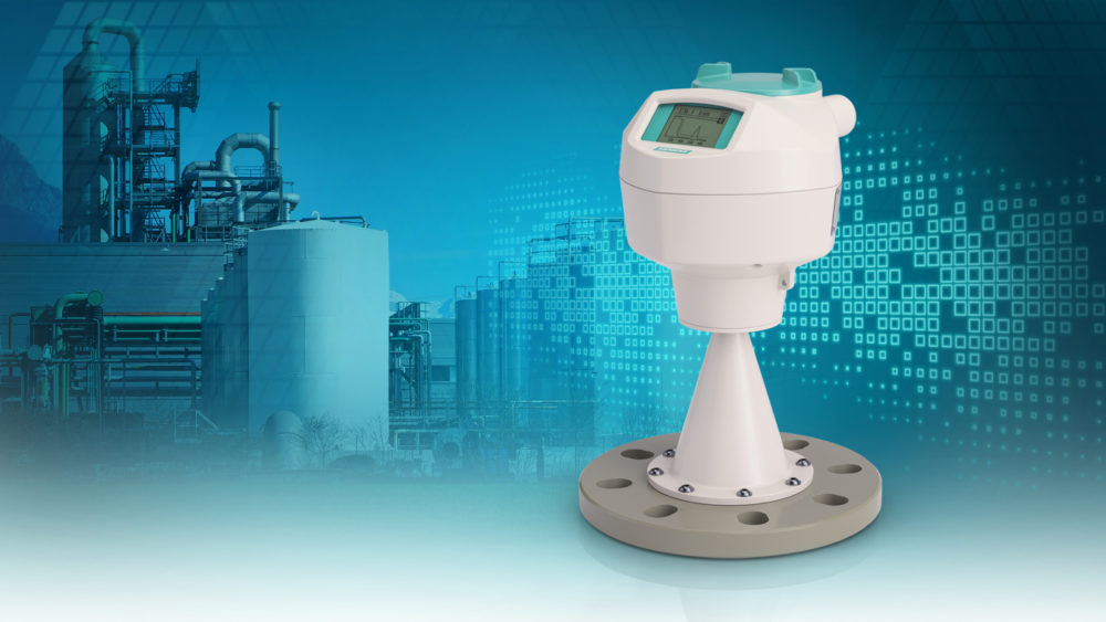
Because the probe must be kept clean and free of grease or other deposits, this approach is unsuitable for materials with a wide range of conductivity.
We’ve included a block schematic of an overhead container water level indicator that employs conducting probes to measure the water level in the tank as a practical illustration of this detection. Priority encoding, BCD-seven sector decoder, seven-segment display, and some other miscellaneous components are used to build this system.
Probes are linked to +5V, and the returning or ground connector is located at the foot of the tank. Using an internal circuitry, nine energetic inputs of the encoder were converted to active-low BCD output, and after that, the water level is displayed in a seven-segment display in percent. Probes brief out when the water level rises, causing the priority encoder to output BCD values to the seven-segment decoder IC, which then displays the information on the seven-segment display.
Automated Systems For Continuous Level Monitoring And Detection
A constant level sensor is the most advanced and can monitor the whole system’s liquid level. As an analog output, this water level sensor directly corresponds to the vessel’s fluid level by measuring the level of the fluid in the vessel across a given range. The output signal is connected to a control loop then linked as a liquid level indicator in order to establish a water level management system. Various sensors are used in this system, such as a gyroscope and accelerometer.
- Sensor Using Ultrasound
- Infrared spectrometer
- Sensor with an Optical Defect
Using An Ultrasonic Sensor For Level Detection And Measuring
It is possible for an ultrasonic level device to detect liquid, solid, or slurries in a vessel using the fundamental time-of-flight concept.
A transducer with high efficiency and an accompanying electrical transceiver make up this liquid level sensor. A water level sensor controller measures the time differential between a sent ultrasonic pulse as well as a reflected echo to estimate the fluid level.
Ultrasonic technologies use waves with a frequency range between 15-200 kHz to broadcast and receive data. Longer distances and strong measurements require equipment with lower frequency, whereas liquid level measurements require devices with higher frequency.
Because they don’t come into touch with the product, ultrasonic sensors are quite a good choice for level measurement because they don’t require any physical contact. There are no moving parts in them.
Additionally, these sensors cannot withstand greater vacuum pressures or temperatures above 170 degrees Celsius.
Radar Level Sensor For Level Detection And Measuring
The premise behind a radar levels measurement system is to time the return journey between both the non-contacting transducers and the liquid level being sensed by measuring the time it takes for a microwave pulse as well as its reflected echo to complete the trip. This electrical signal is then converted by the transceiver into distance/level and presented as an analog or digital signal by the transceiver itself. It is possible to set the output signal of the transducer such that it is either directly or indirectly proportional to the arc length.
Assembled And Operated
This article explains how a radar sensor module works to detect the presence or absence of a substance. The antenna on top of the vessel tank as well as the vessel transmits the radar signals, as seen in the diagram above. The liquid surface reflects the radar signal, which the antenna then picks up and transmits.
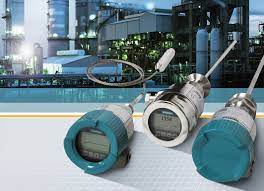
In plastic tanks, this sonar level sensor can monitor liquid levels without coming into touch with the liquid, which gives it great accuracy and low specificity.
This sort of water level sensor has several drawbacks, the most significant of which is its expensive cost, which rises in direct proportion to the sensor’s increasing precision. In addition, the accumulation on the receptor site is particularly sensitive to these sensors.
Radar Level Sensors: The Most Common Uses
Within storage tanks including tank terminals, liquid, and solid levels can be monitored with radar level sensors. Those liquid level sensors may be used in a variety of process environments, including a wide temperature range and pressures.
Optical Sensors For Level Detection And Monitoring
Light receiver and infrared LED form the optical sensor. To detect the level of liquid, an LED emits light that is focused on a prism at the level sensor’s tip. As long as there is no liquid in the tank, you can see through the prism as well as the receiver.
When the water level rises and the sensor prism is submerged in the liquid, the light is scattered outside into the liquid, allowing almost no amount of light to reach the receiver. An external warning or control circuit is activated by the receiver when it detects a change in the signal level.
The optical sensor’s benefits include the fact that it is not in touch with the process and can accurately assess minor level changes.
In addition to their restricted application and potentially exorbitant installation costs, these sensors have other drawbacks.
This article discusses the many types of liquid level sensors, as well as the benefits and drawbacks of each. You can leave your thoughts in the comments area below if you have any more questions.
What Are The Main Kinds Of Level Sensing Methods?
Since the 1970s, water level sensors used in a wide range of industries for a variety of purposes including leak detection and level measuring.
A typical question we get is why clients prefer one technology above another. Some equipment makers may be taken aback by the wide range of level sensing options available, as well as the sophistication of these options.
There are now a variety of inventive, innovative, and clever technologies that may be utilized in place of expensive and cumbersome machinery to do tasks that were before impossible or impractical. Soap including bubbles/foam, milk, including sticky things like glue and ink are now easier to detect thanks to a wide range of level sensor technologies that may be used to monitor liquid levels.
Many individuals may wonder, however, if such technology—or other level measuring device—is actually necessary. Because of the intense competition in the business, no organization wants to take the chance of providing solutions that aren’t operating as well as they may be. This includes cutting prices, improving quality, reducing inefficiencies, and reducing waste.
How To Check The Fluid Level In Different Ways
More precise and dependable level measuring systems are sought by process engineers due to a growing requirement for automated processing systems, better process control, and stricter regulations. Reduced chemical-process variability is made feasible by improved level measurement precision, leading to improved product quality, lower costs, and less waste. There are severe criteria for accuracy, dependability, and electronic reporting in regulations controlling electronic records. To satisfy these criteria, improved level measurement methods have been developed.
There Is A Change In The Level Measurement Technology
Water level sensor: Naturally, the sight glass is the cheapest and oldest commercial-scale measurement equipment still in use today. Sight glasses, which use a manual measuring method, really do have a variety of drawbacks. The transparency material might fail catastrophically, causing damage to the environment, unsafe working conditions for the crew, and even fire and explosion. In the event of a seal failure or accumulation, the liquid level becomes difficult to see. When it comes to installations, traditional eyeglasses seem to be the weakest link in the chain. As a result, newer, more sophisticated technologies are fast displacing them.
The most frequent physical attribute utilized to identify a level surface in other level-detection systems is specific gravity. In order to follow the rises and falls of the vapor in the headspace, you’ll need something to float on top of the liquid. It has also been common practice to infer levels using hydrostatic head readings.
With more complicated physical principles, computers are frequently used to make computations in new technologies. Machine-readable data must be sent from sensors to the control as well as a monitoring system in order to do this. For computer automation, current loops, analog voltages, and digital signals are all useful output signal types from transducers. Even while analog voltages are easy to set up and work with, there is the potential for significant noise and interference.
The most frequent output mechanism nowadays is a 4-20 mA current loop (where the loop current fluctuates with the level measurement), which is the simplest as well as the oldest commercial signal communication method. Signals may be carried over greater distances with much less degradation using current loops.
It’s best to use modern protocols like Profibus or Profibus DP for digital transmissions because they’re more resilient than older ones like Foundation Fieldbus and RS-232. Signals from the most recent transmitters have improved wireless capabilities, permitting them to be delivered across long distances with hardly any degradation of water level sensors.
Digital computer intelligence is required to create the codes in the more complicated encoding forms for modern measuring technologies (such as ultrasonic, radar, and laser). With the necessity for more advanced communication capabilities as well as digital calibration systems, microprocessor-based computers are now being integrated into nearly all level measurement equipment.
There Are Already Established Level-Sensing Methods.
It is assumed that the vapor’s density in the headspace (usually air) is insignificant in comparison to the process fluid’s. We’ll also suppose that the tank contains a single, homogenous process fluid. Multiple immiscible fluids can be mixed in a single vessel using some of these methods.
First, there is the glass gauge for leveling out. Glass gauges were used to measure fluid pressure for more than two centuries and come in a number of forms, including armored and unprotected. The clear glass allows you to view the actual level, which is an advantage of this design. The downside is that glass breaking might cause spillage or endanger the safety of workers.
Is able to float. It’s a straightforward idea: put a buoyant object in the tank that has a specific gravity somewhere in between the process fluids and the headspace vapor’s, and then connect a mechanical system to read out its location. Sinking to the headspace vapor’s bottom, the float is visible above the process fluid. There are still some issues with obtaining accurate level measurements (i.e., reading the float’s location) even though it is a quick and easy solution to finding a liquid’s surface (the fundamental float). Cables, pulleys, and gears were utilized in the early float systems to transmit levels. Magnet-enhanced floats have been more popular during the past few decades with water level sensors.
Devices That Use Hydrostatic Pressure
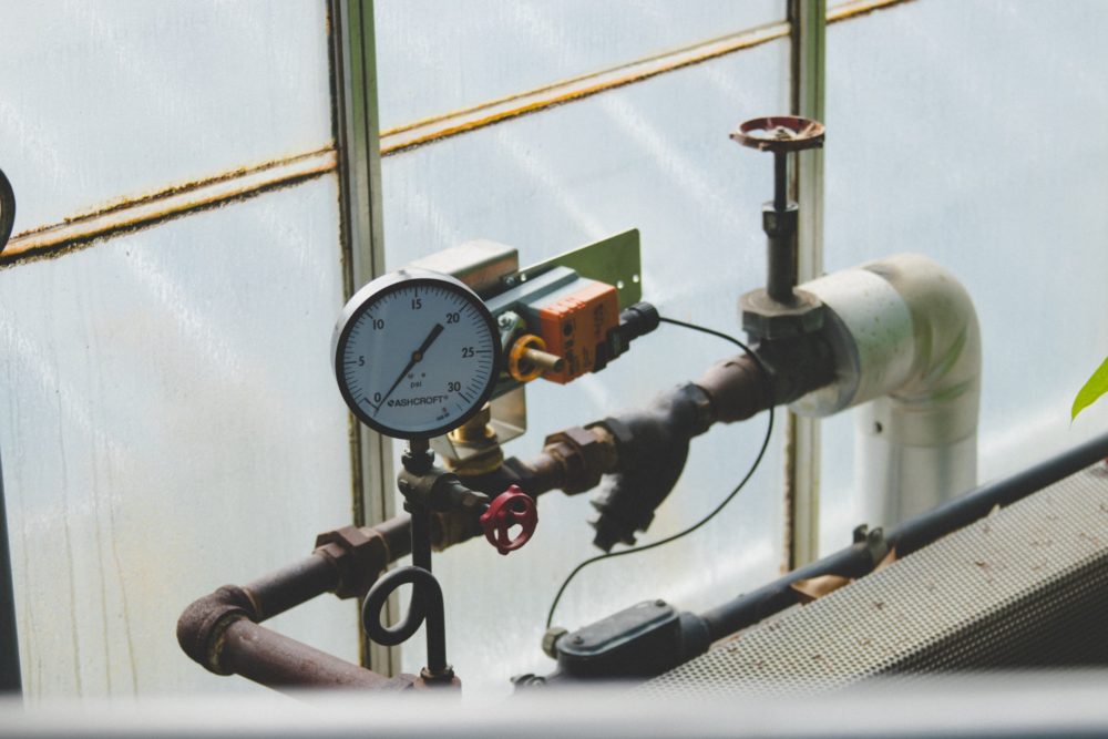
Differential Pressure and Displacers, Bubblers, and Hydrostatic transducers are all transmitters. Consequently, any increase in temperature or pressure will alter the relative density of the liquid or the vapor that surrounds it. Both have a negative impact on measurement precision. It is based on Archmedes’ theory that displacers are used.
If the displacer is lighter than the process fluid, it will sink to the bottom of the fluid and must be at least as dense as the process fluid. The column disperses a quantity of liquid equal to the cross-sectional area of the column multiplied by that of the process liquid level inside the displacer as the liquid mass level rises. An upward force equal towards these displaced capacities ranging by the density of the process fluid pushes upwards towards the displacer and reduces its weight against gravity. Monitored and correlated to level via the transducer, which is coupled to the transmitter.
Bubbler-type level sensor. Atmospheric pressure vessels take advantage of this technology. A purge gas (usually air, although dry nitrogen can also be used if there is a risk of contamination or an oxidation reaction only with process fluid) is carried into the tank by a dip tube with its wide end towards the vessel open.
The pressure in the tube builds until it surpasses the hydrostatic pressure generated by the water level sensor at the dip’s tube exit, resulting in a flow of gas into the tube. A pressure transducer is attached to the end of something like the dip tube to measure the pressure, which is equal to the density of the process fluid multiplied by the distance from the end of the tube to the surface.
Change in total pressure at tank bottom (hydrostatic fluid head plus static pressure within vessel) and vessel head pressure is the most important measurement. The hydrostatic pressure differential equals the density of the process fluid multiplied by the vessel’s height. Atmospheric pressure is used as a standard for the unit. The atmospheric pressure is maintained in the headspace by a vent at the apex.
DP sensors, unlike bubblers, may be employed in containers that are not vented (pressurized). If you connect the low-pressure side to a port in the container above its maximum fill level, you’ll have a working system. The physical circumstances of the process and the transmitter’s position may necessitate the use of liquid purges or bubblers.
Load Cells A load cell with a strain gauge gadget is simply a mechanical supporting member or bracket fitted with one or even more water level sensors that can detect minor distortions inside the support member itself. The bracket bends somewhat when a change in load cell force is applied, resulting in a change in output. From fractional amounts to tonnes of force, accurate load cells have indeed been developed.
The load cell should be integrated into the vessel’s support structure in order to measure level. This force just on load cell grows as the process fluid enters the vessel. In order to determine the fluid level, all that is needed is a load cell whose output is known and the properties of the fluid (particularly, its cross-sectional area and specific gravity).
Many applications benefit from load cells because of their non-contact nature, but they are costly and need a floating substructure for the vessel’s support structure and connected pipework. If the vessel, pipe, and connecting structure are supported by a load system, that weight will also be taken into account. As a result of this total weight, it’s common to see a relatively low percentage of total weight being transferred to the net weight.
Even the expansion of the supporting structure due to unequal heating (e.g., between sunrise and sunset) can be portrayed as level, as can wind load, stiff pipework, and binding from overturn-preventive hardware. When it comes to the original design of the vessel support and pipes, the load cell weighing system needs must be taken into account, otherwise, performance will soon decrease.
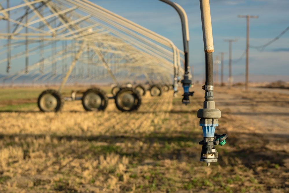
Water level sensor: A wide range of float materials and designs are available from a number of manufacturers, including those that are tailored for the physical properties of the fluid under measured.
To put it another way, the gauges are capable of operating in environments that include high temperatures, high pressure, and chemically corrosive substances. For situations where a buildup is expected, bigger float chambers including high-buoyancy floats are provided.
Engineered polymers like Kynar or exotic metals like Hastelloy C-276 can be used to make chambers, flanges, and process connections. Extreme circumstances, including steam jacketing with liquid asphalt, large chambers for flashing, and temperature solutions for liquid nitrogen as well as refrigerants, can be handled using special chamber arrangements.
Some of the most commonly used metals for high-temperature applications are titanium, Incoloy or Monel, as well as other alloys such as Inconel and Hastelloy. Using magnetostrictive as well as guided-wave radar transmitters, magnetic level gauges may be equipped with 4-20 mA outputs as well as digital communication so that the gauge’s local indication can be relayed to a controller or a control system.
Capacitance Transmitters, number eight. Process fluids often have dielectric constants () considerably different from that of air, which is extremely near to one. These devices work on this fact. Dielectric constants for oils range from 1.8 to 5. Aqueous solutions range from 50 to 80 percent glycol. As the liquid level rises or falls, a change throughout capacitance is required, which may be achieved by the use of insulating or non-insulating rods coupled to either the transmitter or a reference sensor. Because fluid fills the area between plates, the total capacitance increases as fluid levels increase. Capacitance bridges are electrical circuits that measure the capacitance at the system level and offer a continuous level reading.
Advances In Technology
The use of such time-of-flight (TOF) observations to transduce the fluid pressure into a conventional output is perhaps the most important distinction between older continuous liquid-level sensing systems and those presently gaining favor. A water level sensor, as well as a transmitter at the top of the reactor, is often used to measure the distance seen between the water level sensor and just a reference point.
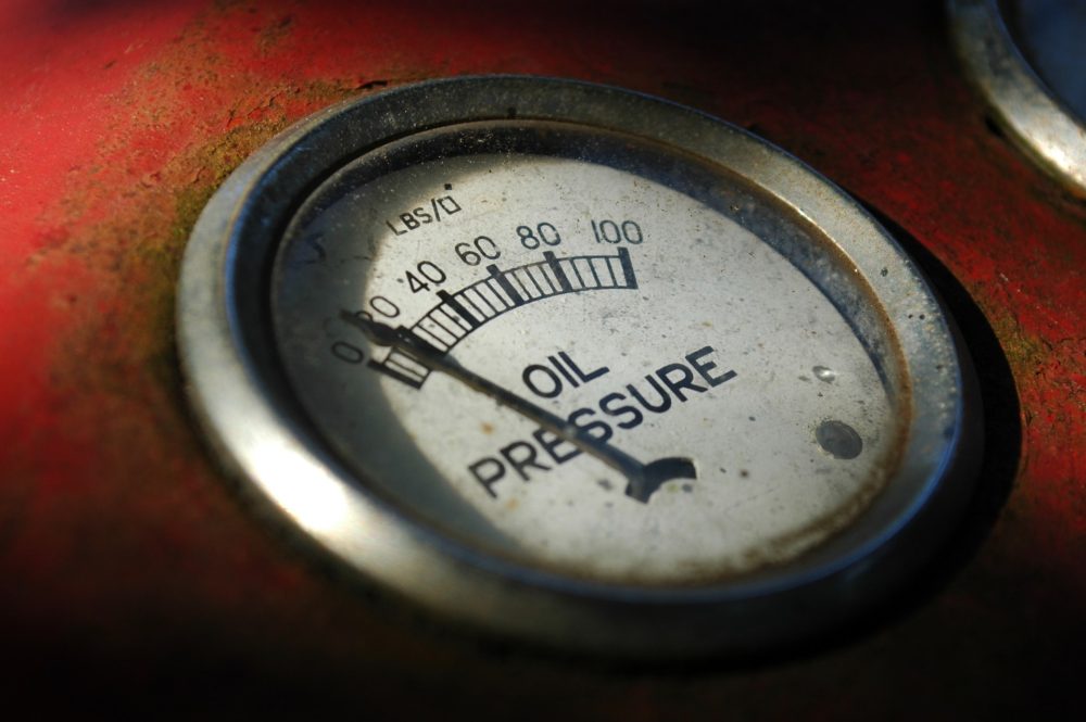
Detectors of Magnetostrictive Level. Magnetostriction, a tried-and-true method for pinpointing the exact location of a float in a magnetic field, may be used to read the level of liquid in a magnetic field. The float is located and reported on using magnetostrictive transmitters, which do not need mechanical linkages.
There are several permanent magnets inside a magnetostrictive system. Piezoelectric sensors at the transmitter are wired up to a tension fixture at the other end of a sensor tubing. Depending on whether the float is in a magnetic or nonmagnetic buoyancy chamber, the tube may run through the center of such float or be next to it outside the buoyancy chamber.
The transmitter uses a brief current pulse to create a magnetic field throughout the sensor wire’s full length in order to find the float. A timing circuit was turned on at the same time. The float’s magnets create a magnetic field that is directly influenced by the surrounding field. The result is a torsional force in the wire, similar to an ultrasonic vibration as well as wave, which returns to the piezoceramic signal at a particular speed during the brief period the current runs. Tensional waves cause an electrical signal to be generated by the water level sensor, which alerts and interrupts the timing circuit as soon as they arrive. The time interval (TOF) seen between the beginning of the current pulse well as the arrival of the wave is measured by the timing circuit.
The transmitter uses this information to identify the specific location of the float and display it as a level signal. Because the signal velocity is predictable and constant regardless of process parameters such as climate and pressure, this technique has a number of benefits. The only moving portion is the float, which rises and falls with the surface of the fluid.
Ultrasonic Level Transmitters, tenth. There are a number of ultrasonic distance sensors that use ultrasound pulses traveling from transducers to the liquid then back to determine the transducer-surface distance (TOF). Transit times for these sensors are less than six milliseconds per meter. The headspace gas combination and its temperature affect the sound speed (340 m/s with air at 15 ° C., 1115 fps at 60 ℉). Despite the fact that the temperature of the sensor is corrected, this technique is only capable of measuring atmospheric pressure in air or nitrogen.
Laser Level Transmitters, number 11. Lasers are based on the same idea as ultrasonic water level sensors and are used for solids, slurries, and opaque liquids such as unclean sumps, milk, as well as liquid styrene. However, instead of utilizing the speed of sound, they utilize the speed of light to determine the level (see Figure 9). If you’ve ever wondered what’s going on under the surface of your process liquid, a laser transmitter located on top of a vessel can help.
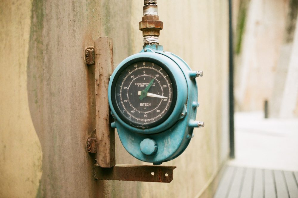
Radar Level Transmitters, 12th Edition. Through-air radar systems use either a horn and perhaps a rod antenna just at top of a ship to transmit microwaves to the ground. A timing circuit measures the time it takes for the signal to return to the antenna from the fluid surface and determines the distance towards the fluid level (TOP).
The dielectric interaction of liquid is the most important factor in radar technology. Microwave (radar) radiation is highly reliant on the fluid’s dielectric constant, and low Er means that most of it enters or goes through. An outstanding reflection occurs when Er changes or discontinues in water (Er=80).


 Water Level Sensor Measuring
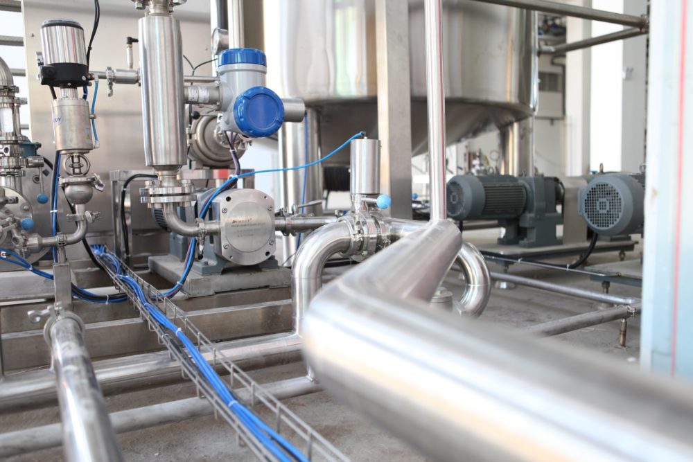 Capacitance Sensor Level Detection But Also Measurement