Arduino water level sensor: Measurement technology company Pulsar Measurement has developed a level sensor series called the dB Transducer. Tier, loudness, open channel flow, pump authority, and difference level measurement are all provided by our ultrasonic level sensors, which range in length from 3 m (9.8 feet) to 50 m (164 feet).
In the dB ultra – sonic transducer range, precise and reproducible ultrasonic technology is at play. Acoustic power generated by a low-power design can be used in a wide range of challenging applications, from wastewater treatment to industrial processes.
They can be installed with no interruption to service and no need for time-consuming maintenance because of the quasi design of dB ultra-sonic sensors In addition to submergence shielded ultrasonic level sensors, Pulsar Measurement’s range of ultrasonic level sensors includes Polymeric versions for installed sensors in hazardous locations.
When your measurement needs to change, you won’t have to change your system. All dB transducers can be retrofitted with a whole Pulsar Measurement controller range.
When it comes to Mettler process instruments as well as the problems they solve, Jasper Engineering has unmatched industry experience.
In the chemical, food and beverage, biotechnology, and pharmaceutical industries, Mettler-Toledo Process Data analysis is a global leader in ionic strength, ORP, disintegrated and gaseous oxygen disintegrated Carbon dioxide, and ozone, conductivity, and sedimentation remedies for advanced process measurement systems.
 What You Need To Know About Arduino Water Level Sensor
Bioburden and total organic material analysis tools, gas sensing and analyzers, and analysis tools for silica, sodium, chloride, and sulfate are all manufactured by the company.
Chemical processes and hygienic/sterile applications are its primary focus because they demand high-quality in-line measurement of such variables using high-quality products like sensors, transmitters, cleaning systems, and services.
Tank Gauges And Liquid Level Indicators
Liquid Level Indicators and Liquid Level Gauges are manufactured by Innovative Components for a variety of fluid level sensing and quantification applications. For apps that do not have access to electrical power, we provide precision level sensors and mechanical indicators. Robotic Liquid level tape measures (LLTM) provide a complete to empty tank reading via a tape measure. Displaying filled to vacant measurements via bright LED lights, the Threshold Central defender Indicator (LKI series) features a multi-point system. There is a Point Level Watch (CLM series) that provides accurate readings of every 1/4′′ of movement in the level. Using Ultrasonic Distance sensors in tanks up to 30 feet deep is the most accurate method. Click on the classifications below to learn more about Liquid Level Metrics and Arduino water level sensors.
The LTM Series Mechanical
You can tell exactly how much fluid is remaining in your tank with these mechanical indicators. Ideal for use with mobile storage tanks, hazardous environments, or remote locations without access to electricity, these units can be found all over the world. Polypropylene and stainless steel are the most common materials, but they’re also available in a variety of other combinations. You can take a reading by simply pulling the measuring tape out from the stem till you feel a permanent magnet lock up between both the float and the tape measure.
The Lki Series Of Multi-Point Cameras
If you have tanks or totes, these multi-point gas pressure indicators are a good choice. A bright, easy-to-read LED tank level indicator is provided. All stainless steel, stainless and buna, and polypropylene glide level indicators are available. Relays for elevated/low alarms or flush control can be added.
The Clm Series – Continuous Level
There are vertical float-type sensors for storage tanks and vessels that need accurate liquid tank level measurement. All stainless, stainless, and Buna or polypropylene options are available. The sensor is a three-wire potentiometer that changes resistance every 1/8″ of level change. Display the precise fluid level gauge reading using a digital panel meter or transmitter conditioner which outputs a 4-20mA signal.
The Uls Series Of Ultrasonics
Using these non-contact ultrasonic distance sensors, you can measure distances of up to 30 feet. Tank farms and other large outdoor storage facilities benefit greatly from their use. For liquid or solid detection, they come with a variety of output options.
The water sensor is simple to use and only requires three pins to connect. There are three pins: floor, +5V, and the signal. It is possible to connect the signal pin to an analog output on your Arduino water level sensor. Several copper lines on the analog sensor board are not connected, but water bridges them when the sensor is submerged.
Water that has been purified is not conducive in any way. Nutrients and contaminants in water are what make it conductive, not the water itself. To get accurate readings, you may have to change the results in the code depending on the type of water you use. This is important to know. Your water’s impurities are what we’re really interested in reading. There is less resistance when more traces are bridged.
With pretty standard public water supplies, reading the output of the sensor with an analog signal pin of Arduino will yield a numeric value between 0 and 500.
 Arduino Water Level Sensor
For This Project, The Parts List.
You’ll Need The Following Items To Complete This Project:
Both the Arduino Uno and Arduino Mega 2560
- The detector of Water Level (Leak Detection Sensor)
- Display of LCD characters (optional)
- Ten thousand ohms (optional)
- Wires and a Breadboard
Sensing The Water Level With The Arduino
It’s a breeze to connect the water level sensor. Connect it using the following circuit board and then use the serial console or write your own code to interact with the device. If you’re going to use this sensor in a remote location, make sure the Arduino water level sensor and the sensor have a common ground. A transformer or a USB port cannot provide common ground. You should ensure that the Microcontroller Function generator pin is connected somewhere within your project to the sensor’s GND pin.
- The Arduino A5 Receives Water Sensor Signals.
- Arduino 5V to Water Sensor +5V
- Arduino GND to Water Sensor GND
If you’d want to follow our complete construction and outcome to the Lcd display, please refer to our Arduino wiring tutorial. For those of you who are already familiar with them, here is a diagram.
Wiring Diagram For Arduino Water Level Sensor With Lcd Display
Example Of Micro Controller Water Level Code (Serial Console)
The above code will print the water level sensor’s output to your serial console if you don’t have (or don’t want) a Liquid crystal display personality display in your project. The Microcontroller water level sensor can be used in a variety of ways, and this code will help you get started. There are a few points to bear in mind when using this code:
In order to run it more frequently, you must change the delay time. However, the sequential output routine will be your limit. You must disable serial output if you want to perform a check faster than 100 milliseconds.
If you have a lot of minerals in your water, you may need to change the numbers here. Depending on the water, the detector could be somewhat sensitive. Minerals, not pure water, are what make this possible. In my neighborhood, the figures I used are effective.
What The Project Has Finished
You should be able to see the water level on your LCD screen or serial console as you reduce it into a drink of tepid water.
The Arduino Water Level Sensor Uses
The water sensor is more flexible than you might expect and can be used for a wide range of applications. So, here are some ideas for you to experiment with:
Infrared water level sensors for water heater pans. When these haters get older, they’re more likely to leak. It’s possible to detect when water is present in an otherwise dry pan by inserting a sensor.
For under-sink links, this is also true. When the house is unoccupied most of the year. This leakage detection device can be connected to the internet using a Wired Cover (or WiFi) to send an email when water is detected.
Despite the fact that it wasn’t intended for soil moisture measurements, it does a decent job. You’ll have to explore the numbers, but this machine can be used to decide whether or not plants need liquid and to activate a water hose to hydrate them.
- Heater leak detection using an Arduino water level sensor
- Arduino sensor for detecting leaking toilets
Hopefully, you’ve benefited from this project! Let us know how we can assist you by leaving a comment below.
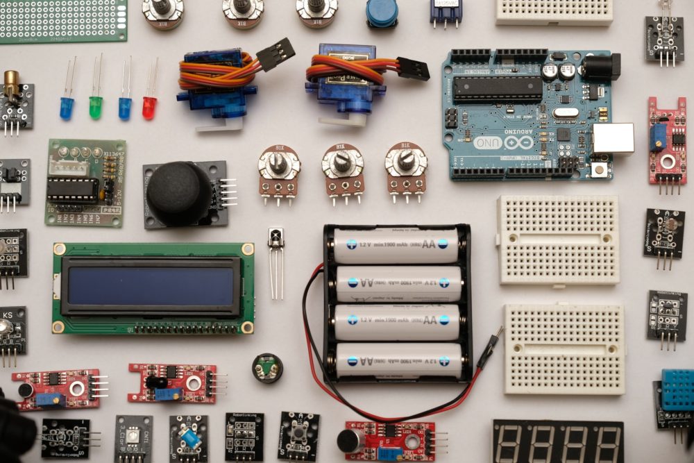
What Is The Process Of Making An Arduino Water Level Detector?
Ultrasonic or Ping sensors are used to determine the water level in the tank with this Arduino water indicator. Sonar is used by the Ping sensor to determine distance. Using the time it takes for the echo to return, a distance to the target can be determined using an ultrasonic pulse. The Ping sensor generates a variable-width pulse based on the target’s proximity. The microcontroller uses this information to determine the level of water and display it using a series of LEDs.
If you have an Arduino board, you can use this project to interface directly with an Arduino microcontroller micro-controller on a circuit board. We recommend checking out Jeff’s tutorial on how to use an ultrasonic sensor with an Arduino water level sensor.
Assembling The Links
Going to follow the attached Fritzing diagram, fill up the loop on a PCB or breadboard. This is for an 8-bits Arduino on a breadboard. If you want to start making your own Arduino board, users can obey Mayoogh Girish’s tutorial. Make the LEDs and ultrasonic sensor connections as shown below unless you use an Arduino board.
Putting The Code On The Internet
You can use an Arduino board or an ATMega328P microcontroller to fire the software for the Microcontroller water level indicator.
Connecting the Water Tank’s Ultrasonic Sensor
The Ping sensor should be fixed so that it is facing the tank’s water. LEDs on the central control board allow it to be installed in any convenient location in the home. The Ping sensor can be connected to the circuitry using any multi-cored cable (ethernet cable). Keep in mind that the distance between components should not exceed 20 meters.
One Contactless Microcontroller water level sensor is now ready for use. Simply connect a battery.
Using the diffused-silicone principle, the GLT530E is a thermally insulated submersible level transmitter with a diameter of 17/19mm. A piezoresistive pressure sensor, a special PCB component, and a stainless steel housing make up the device. Its integrated design and standardized signal output make it easier to operate and control automation systems at worksites. Using a special vented cable that is hermetically sealed to its housing ensures that the transmitter can be used in fluids that are consistent with its construction material for an extended period of time.
The GLT530E Threshold Transmitter is small, light, and has long-term stability that makes it ideal for use in confined spaces. Measurement and control of liquid levels in the fields of medicine, metalworking, power plants, mining and fresh water and drainage, hydrology exploration, etc. are all possible applications of this Arduino water level sensor.
Build- is one of the world’s leading sensor companies, with cutting-edge sensor solutions that enable customers to transform their ideas into smart, connected devices. In addition to automotive, industrial, and commercial transportation, aerospace, and defense applications, TE’s sensor solutions are used in a wide range of other industries, including medical and consumer applications.
In addition to automobiles, stream, force, photo optic, and pressure sensors and transmitters, we also provide differential sensors and differential transmitters as well as a wide range of other sensor solutions.
Liquid – solid, non-contact level sensors from the Tecmark Tv show EP1226 can be used in a wide range of applications. Designed to be used in accordance with Tecmark EP1227, EP3000, as well as West brom timer, the accumulated sensor is housed in a low-profile enclosure. Non-metallic containers are recommended for use with this product. The sensor is attached to the container’s dry side using double-sided adhesive-backed foam tape.
 Typical Uses For
Liquid level sensors from the EP1226 series monitor a wide range of applications, including hydrotherapy baths, residential and business applications as well as commercial spas, swimming pools, and drain pumps.
These detectors are used for a variety of places where water levels and flow need to be monitored such as in irrigation tanks, hot tubs, and fish ponds. In this tutorial, I’ll demonstrate how to connect this sensor to an Arduino board.
When The Sensor Detects A Drop-In Water Level, What Does It Do?
The permeability of the water in which it is submerged is what causes this sensor to react. Water’s conductivity is proportional to the concentration of impurities it contains, so pure water has no conductivity.
In the sensor, ten copper traces are present, four of which are used to supply power and five of that which are used to detect signals. When submerged, the water consists of a resistor that changes its resistance depending on the water level.
When a sensor is submerged in more water, it will have a higher conductivity and a lower resistance, which is inversely proportioned to the water depth. In order to identify the water level, a microcontroller interprets the sensor’s output voltage, based on the resistance.
This same water level sensor is being connected to the Arduino water level sensor.
Due to the fact that the conductivity varies, it is necessary to calibrate this same water level sensor before using it.
You can see the schematic below that shows how each of the three components is connected to each other.
Submerging the sensor one by one into a container of water, the serial monitor displays the sensor’s various values. Values should start at zero when the sensor isn’t submerged and rise as the detector is submerged deeper.
Microcontroller and serial monitor calibration of a water level sensor
We can choose bottom and top threshold values from the serial monitor values. Using the image above as an example, we can set our bottom and top thresholds at 310 and 510, respectively.
A straightforward water monitoring system can be constructed.
For example, we can use the sensor for detecting the threshold of water in different containers by connecting it to an I2C LCD and adjusting the thresholds in the correlating code.
The link below will take you back to a previous post that explains how to use an I2C LCD with an Arduino.
How to connect an I2C LCD to an Arduino using SPI
LCD display for monitoring water level
As you can see from the schematic, the sensor’s power terminal is now connected to a digital pin rather than the Arduino’s 5V pin. This is done in order to slow down the rate at which the copper corrodes when soaked in water and driven for extended periods of time.
Using a digital pin high, we just strengthen the trace amounts while we are trying to read from the sensor. By doing this, the sensor’s lifespan will be extended.
Arduino Code For Monitoring Water Levels.
Calibration-Dependent Threshold Values Are A Major Problem In The Code Below.
In order to determine the liquid level, the eTape Fluid Level Sensor utilizes a resistive output. Electronic control systems can be easily interfaced with, and clunky mechanical floats are no longer required. When the eTape sensor is submerged in a fluid, the hydrostatic pressure compresses its envelope. As a result, the sensor’s resistance changes in direct proportion to the sensor’s height above the fluid’s surface. As the liquid level drops, the sensor’s resistor output rises, and vice versa. The sensor’s output resistance decreases with the increasing liquid levels.
When it comes to measuring liquid levels, we have never seen anything quite like this sensor. If you have an aquaponics, aquarium, waterfall, or pool controller, or rain tube, this sensor could be a useful addition. In addition to the 12″ sensor, we’ve included a connector and a 560-ohm resistor in the package. Rather than solder directly onto the sensor pins, use the plug and plug it in to avoid the risk of damaging them.
A microcontroller or Arduino water level sensor ADC pin can easily read the sensor because it is resistive. You can find a quick-start guide in the tutorials section.


 What You Need To Know About Arduino Water Level Sensor
 Arduino Water Level Sensor
 Typical Uses For